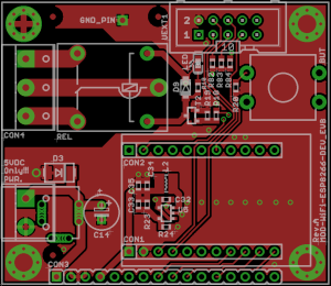
ESP8266-EVB is complete and run in production, we hope to have it assembled and tested in stock before Christmas 🙂
What we got here?
- MOD-WIFI-ESP8266-DEV module with soldered connectors
- Base board with female connectors for accepting MOD-WIFI-ESP8266-DEV
- Power Relay 10A/250VAC connected with driver to GPIO output
- User Button connected to GPIO input
- Power supply jack – 5V input
- DCDC power converter to 3.3V to supply ESP8266 and UEXT modules with up to 1.5A current
- UEXT connector where you can connect different modules and sensors from Olimex
- GPIO CON3 with 16 pins where all ESP8266 resources are available
- 4 mounting holes
The price of ESP8266-EVB (which includes MOD-WIFI-ESP8266-DEV) will be EUR 12.00 for single quantity and will drop under EUR 10 for 50+ order.

Dec 04, 2014 @ 18:54:16
OK. Great for the Hobbyist I guess, but what’s going with the RT5350F boards 😀 if you don’t mind asking under a different topic 😀 It’s just a similar product, and whoever follows this one (8266) will be most certainly interested in the other 😀 Thanks for your time and hard work, Olimex 🙂
Dec 04, 2014 @ 18:59:08
RT5350F had several revisions, now software works reliable and also is in production, probably will be in stock in January as the board is more complex
Dec 04, 2014 @ 19:14:39
Where is usb power?
Dec 04, 2014 @ 19:18:54
who said USB power?
Dec 04, 2014 @ 20:22:37
how much would it cost to replace the 5v power connector and/or replace it with a microusb one?
Dec 04, 2014 @ 20:47:25
do not get me wrong but driving relays and sourcing 2A from usb port is worst idea ever 🙂
Dec 04, 2014 @ 21:12:30
The esp8266 does not suck 2A, see:
https://nurdspace.nl/ESP8266#Power
But you are right, adding some components on the board might suck more power.
Dec 04, 2014 @ 21:45:50
it’s not just the ESP8266 on the board, there is RELAY and there may be different UEXT boards connected like 4 more relays with MOD-IO board
we put 2A DCDC regulator just to have large power budged why to limit it to few hundreds of mA with USB power???
Dec 04, 2014 @ 19:19:02
Great product. Do you plan do design Wifi module based on WICED platform (with STM32F205RG or other MCU) or add Broadcom wifi chip to some STM32 board ?
There is GNU SDK available …
Dec 07, 2014 @ 22:46:12
Otherwise, do you know how to attach an SD card to the SDIO interface of the chip? I cannot find any documentation anywhere.
Dec 09, 2014 @ 08:13:17
8.4.1 Master SI / SPI Control (Optional)
The master serial interface (SI) can operate in two, three or four-wire bus configurations to control the EEPROM or other I2C/SPI devices. Multiple I2C devices with different device addresses are supported by sharing the 2-wire bus.
Multiple SPI devices are supported by sharing the clock and data signals, using separate software controlled GPIO pins as chip selects.
The SPI can be used for controlling external devices such as serial flash memories, audio CODECs, or other slave devices. It is set up as a standard master SPI device with 3 different enable pins:
SPI_EN0,
SPI_EN1,
SPI_EN2.
Both SPI master and SPI slave are supported with the latter being used as a host interface.
SPI_EN0 is used as an enable signal to an external serial flash memory for downloading patch code and/or MIB-data to the baseband in an embedded application. In a host based application, patch code and MIB-data can alternatively be downloaded via the host interface. This pin is active low and should be left open if not used.
SPI_EN1 is usually used for a user application, e.g. to control an external audio codec or sensor ADC, in an embedded application. This pin is active low and should be left open if not used.
SPI_EN2 usually controls an EEPROM to store individual data, such as MIB information, MAC
address, and calibration data, or for general use. This pin is active low and should be left open if
not used.
Dec 09, 2014 @ 13:28:41
@Ratibor SPI is not SDIO.
Dec 09, 2014 @ 13:30:05
Some competition:
http://www.aliexpress.com/item/Esp8266-ESP-12-wifi-module-esp8266-serial-wifi-coexistence-full-AP-test-board/32243938529.html
Dec 09, 2014 @ 17:13:30
Is the RTC pin connected to RST ?