A13 processor have no HDMI and VGA output as his big brother A10, so we had to work out something using the LCD interface it have.
We browsed IC video DACs and there is plenty of them, but they are expensive and didn’t fit well OLinuXino low cost concept, so we decided to give a try and make simple R ladder video DAC.
A13 LCD interface is 18 bit this means we will need 3 channels x 6 bit Video DAC.
All VGA monitors have 75 ohm terminator on their input lines and the video signal is 0.75V for white level and 0V for black. So knowing this we could make resistor ladder DAC with R, 2R, 4R, 8R, 16R, 32R connected in parallel with RGB 0-5 bits. The values are easy to calculate when we know the LCD buffer output voltage 3.3V and the voltage we want to have when all bits are “1” i.e. 0.75V. The resistors using the 1% precission values picked were 549 ohm, 1050 ohm, 2180 ohm, 4370 ohm, 8660 ohm, 17800 ohm.
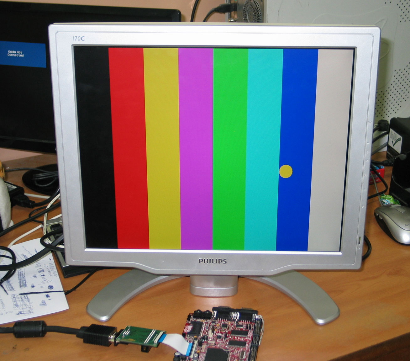
The adapter was routed and pcb prototypes were run. The assembled adapter was attached to LPC1788 board with 4.3″LCD with tweaking the output to match VGA lock frequency and the result was perfect.

The picture which appears on LCD was color stripes with small ball which you can move by tilting the board (using on-board accelerometer), as you can see from the picture the colors are perfect and image is standing still with no glitches and jitters.
So now we have low cost VGA solution for our A13-OLinuXino and can move forward with the PCB schematic finish and routing. Note that the VGA signals go through buffers which are gated i.e. we can enable and disable the VGA output and A13-OLinuXino will be able to work with both LCDs and VGA.
EDIT: schematic is included here below:


Jun 12, 2012 @ 15:26:47
Does this adapter schematic will be available at github rep?
Jun 12, 2012 @ 15:37:03
it’s simple 3×6 resistors atached to RGB signals 🙂
Jun 18, 2012 @ 01:59:11
Where we can find these RGB resistors? :))
Jun 18, 2012 @ 08:01:56
from the usual place where you buy 1% resistor 🙂 these are standard E96 values, so every resistor manufacturer can manufacture on request
Jul 22, 2012 @ 03:23:06
Would this work with i.MX233 controller? I am playing right now with an olinuxino-maxi and I see on its gpio’s some LCD pins. I think the only problem are drivers?
Sorry for my bad English. I am Bulgarian, too. Greets, Angel Dimitrov.
Aug 16, 2012 @ 10:05:24
HI there,
I am trying to interface VGA monitor to a ARM9 based controller. It has in built LCD controller(AT91SAM9G45). The setup works with a 640 x 480 pix. LCD. When i try to interface the same LCD pins(R,G,B with VSYNC and HSYNC) I get nothing on the screen. Do I need to change some parameters in LCD driver in OS(Linux 2.6.30)? I am using IC 74ACT244. Thanks in advance
Pankaj C
Aug 16, 2012 @ 10:27:42
check the signals timing with oscilloscope
Aug 16, 2012 @ 11:09:46
Hi
Thakns for early reply. But I do not have any idea on how shoud the signals look like on CRO, I do not have any reference.
Aug 16, 2012 @ 11:55:14
VSYNC is 15KHz and HSYNC is 25Hz.
Aug 16, 2012 @ 14:05:09
Hey!!
I got on the display.. but only green component 😦 . Still need help.
/*****************VGA********************************/
{
.name = “TX09D50VM1CCA @ 60”,
.refresh = 60,
.xres = 640, .yres = 480,
.pixclock = KHZ2PICOS(25180),
.left_margin = 48, .right_margin = 16,
.upper_margin = 33, .lower_margin = 10,
.hsync_len = 96, .vsync_len = 2,
.sync = 0,//FB_SYNC_DE_HIGH_ACT,
.vmode = FB_VMODE_NONINTERLACED,
.flag = 0,
},
/***************************************************/
Aug 18, 2012 @ 08:24:35
if you get only green component check if you have red and blue video signals connected properly
Aug 21, 2012 @ 06:00:42
I have connected all the color pins properly. But I think the IC which I have mentioned in my earlier post is the problem. It is a 5 V driven IC and the voltage levels of color bits from controller are 1.8 V. That may the problem. Anyways.. I have placed a ordered for the LV series of IC.
Any other idea from you may help me.
Aug 16, 2012 @ 12:12:40
What is the pixel clock for VGA monitors? do I need to modify “.pixclock = KHZ2PICOS(34000),”. This is for tft lcd with 640 x 480.
Apr 14, 2013 @ 18:04:11
Hey guys!
Can you guide me how to connect a 24-bit LCD controller to a CRT display? I’m going to use the same schematics as you have here but don’t know the resistors values. Please help!
Jan 28, 2014 @ 10:00:15
For one of my projects I am using LPC series ARM7 uCs. I want to convert all the 24 bit color signals to VGA/HDMI. Will you please suggest me any Video DAC IC with circuit diagrams for this purpose. Also I want to use the full 1024 X 768 pixels.
Thanks in advance.
Aug 17, 2014 @ 02:12:00
I`m trying to connect my broken tablet to a vga input device like lcdtv or monitor , the tablet output is ( AT090TN10 LCD Display Screen for 9 Inch Android Tablet PC 800x480px 50Pin ) does this circuit works for me ?
Aug 17, 2014 @ 02:14:02
i forgot to say my tablet is using allwiner A13 chip .
Apr 14, 2018 @ 03:55:02
did you find solution for that ?
Oct 27, 2018 @ 09:50:21
Hello, i have a 5″ tft picture frame and i want to use the pic frame as dual screen with pc. your schematic will work in this case?