
iCE40-IO is Open Source Hardware snap-to module for iCE40HX1K-EVB which adds VGA, PS2 and IrDA transciever.
In this tutorial you will learn how to generate VGA video signals, how to capture PS2 keys and how to move object on the video screen.
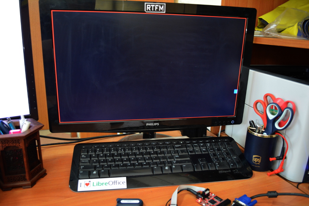
Here is my setup:

I have iCE40HX1K-EVB snap to iCE40-IO with PS2 keboard and VGA connected to it and OLIMEXINO-32U4 as programmer
The tutorial project is on GitHub. Let’s first see example_0.v
Yesterday after sharing my experience with Verilog to silently define signals which you could have type by mistake, there was comment by Andrew Zonenberg, who wrote that you can tell Verilog to consider this error by adding “`default_nettype none” as your first line code. I check and it works fine, so I will use it in all my further sources 🙂 Thanks for the tip Andrew!
The code starts with:
   `default_nettype none //disable implicit definitions by Verilog

   module top( //top module and signals wired to FPGA pins
    CLK100MHz,
    vga_r,
    vga_g,
    vga_b,
    vga_hs,
    vga_vs,
    ps2_clk,
    ps2_data
   );
here we define top module and what physical signals we will use, these are the CLK100Mhz, VGA R,G,B, H-sync, V-sync, ps2 clock and data
then we must define each of them:
   input CLK100MHz; // Oscillator input 100Mhz
   output [2:0] vga_r; // VGA Red 3 bit
   output [2:0] vga_g; // VGA Green 3 bit
   output [2:0] vga_b; // VGA Blue 3 bit
   output vga_hs; // H-sync pulse
   output vga_vs; // V-sync pulse
   input ps2_clk; // PS2 clock
   input ps2_data; // PS2 data
as you can see VGA R,G,B signals are 3 bit registers, this way we defini VGA to have 9bit color or 512 different colors
the next part use new keyword parameter, this is how the constants are defined in Verilog:
  parameter h_pulse = 96; //H-SYNC pulse width 96 * 40 ns (25 Mhz) = 3.84 uS
  parameter h_bp = 48; //H-BP back porch pulse width
  parameter h_pixels = 640; //H-PIX Number of pixels horisontally
  parameter h_fp = 16; //H-FP front porch pulse width
  parameter h_pol = 1'b0; //H-SYNC polarity
  parameter h_frame = 800; //800 = 96 (H-SYNC) + 48 (H-BP) + 640 (H-PIX) + 16 (H-FP)
  parameter v_pulse = 2; //V-SYNC pulse width
  parameter v_bp = 33; //V-BP back porch pulse width
  parameter v_pixels = 480; //V-PIX Number of pixels vertically
  parameter v_fp = 10; //V-FP front porch pulse width
  parameter v_pol = 1'b1; //V-SYNC polarity
  parameter v_frame = 525; // 525 = 2 (V-SYNC) + 33 (V-BP) + 480 (V-PIX) + 10 (V-FP)

  parameter square_size = 10; //size of the square we will move
  parameter init_x = 320; //initial square position X
  parameter init_y = 240; //initial square position Y
for VGA timing we will use 25Mhz clock which is made by division by 4 of CLK100Mhz:
  reg [1:0] clk_div; // 2 bit counter
  wire vga_clk;

  assign vga_clk = clk_div[1]; // 25Mhz clock = 100Mhz divided by 2-bit counter

  always @ (posedge CLK100MHz) begin // 2-bt counter ++ on each positive edge of 100Mhz clock
   clk_div <= clk_div + 2'b1;
  end
vga_clk is the bit2 of clk_div which is incrementing on each positive edge of 100Mhz clock
then we define the registers which will hold the VGA signals:
  reg [2:0] vga_r_r; //VGA color registers R,G,B x 3 bit
  reg [2:0] vga_g_r;
  reg [2:0] vga_b_r;
  reg vga_hs_r; //H-SYNC register
  reg vga_vs_r; //V-SYNC register

  assign vga_r = vga_r_r; //assign the output signals for VGA to the VGA registers
  assign vga_g = vga_g_r;
  assign vga_b = vga_b_r;
  assign vga_hs = vga_hs_r;
  assign vga_vs = vga_vs_r;
we do want the video generation to start after some time not immediately, and for this we will use two signals:
  reg [7:0] timer_t = 8'b0; // 8 bit timer with 0 initialization
  reg reset = 1;
8 bit timer will make the necessary delay, reset is internal signal and have nothing in common with the reset button on the board
these registers will hold info where the “video beam” is when the video is generated, we need two of them as one will hold the complete frame even with some of “invisible” video frame, the other just the visible part
  reg [9:0] c_row; //complete frame register row
  reg [9:0] c_col; //complete frame register colum
  reg [9:0] c_hor; //visible frame register horisontally
  reg [9:0] c_ver; //visible frame register vertically
this signal flags if the display is enabled or disabled
reg disp_en; //display enable flag
these registers will hold the center coordinates of the visible square we draw on the screen:
  reg [9:0] sq_pos_x; //position of square center X, Y
  reg [9:0] sq_pos_y;
these registers will hold the upper left and down right coordinates of the square we draw:
  wire [9:0] l_sq_pos_x; //upper left and down right corners of the square
  wire [9:0] r_sq_pos_x;
  wire [9:0] u_sq_pos_y;
  wire [9:0] d_sq_pos_y;

  assign l_sq_pos_x = sq_pos_x - square_size;
  assign r_sq_pos_x = sq_pos_x + square_size;
  assign u_sq_pos_y = sq_pos_y - square_size;
  assign d_sq_pos_y = sq_pos_y + square_size;
the next registers are for reading the PS2 keyboard:
  reg [3:0] ps2_cntr; // 4-bit PS2 clock counter
  reg [7:0] ps2_data_reg; // 8-bit PS2 data register
  reg [7:0] ps2_data_reg_prev; // previous 8-bit PS data register
  reg [7:0] ps2_data_reg_prev1; // previous previous 8-bit data register
  reg [10:0] ps2_dat_r; // 11-bit complete PS2 frame register

  reg [1:0] ps2_clk_buf; // PS2 clock buffer
  wire ps2_clk_pos; // PS2 positive edge detected signal

  reg u_arr = 0; //PS2 arrow keys detect flags
  reg l_arr = 0;
  reg d_arr = 0;
  reg r_arr = 0;
the 4-bit counter is for PS2 clock, the three data registers hold three sequential key codes as some keys are transmitted as two bytes when press and three when released
ps2_clk_buf is used to detect rising edge of the PS2 clock:
  assign ps2_clk_pos = (ps2_clk_buf == 2'b01);
         // edge detector positive edge is when the buffer is '10'
25Mhz clock is used to detect PS2 clock and data:
  always @ (posedge vga_clk) begin // on each positive edge at 25Mhz clock
    ps2_clk_buf[1:0] <= {ps2_clk_buf[0], ps2_clk};
             // shift old value left and get current value of ps2_clk
    if(ps2_clk_pos == 1) begin // on positive edge
     ps2_cntr <= ps2_cntr + 1;
     if(ps2_cntr == 10) begin
         // when we got 10 clocks save the PS2 data to ps2_data_reg,
         // ps2_data_reg_prev and ps2_data_reg_prev1
      ps2_cntr <= 0; // so we have last 3 data values captured from PS2 keyboard
      ps2_data_reg[7] <= ps2_dat_r[0];
      ps2_data_reg[6] <= ps2_dat_r[1];
      ps2_data_reg[5] <= ps2_dat_r[2];
      ps2_data_reg[4] <= ps2_dat_r[3];
      ps2_data_reg[3] <= ps2_dat_r[4];
      ps2_data_reg[2] <= ps2_dat_r[5];
      ps2_data_reg[1] <= ps2_dat_r[6];
      ps2_data_reg[0] <= ps2_dat_r[7];
      ps2_data_reg_prev <= ps2_data_reg;
      ps2_data_reg_prev1 <= ps2_data_reg_prev;
    end
    ps2_dat_r <= {ps2_dat_r[9:0], ps2_data}; // data shift left
   end
at this point we have detected when the PS2 keyboard start sending data and captured the transmitted data
here is where we detect is left, right, up and down keys are pressed:
  if(ps2_data_reg_prev1 == 8'he0 && ps2_data_reg_prev == 8'hf0) begin
      // 0xE0 0xF0 sequence means key released
    if(ps2_data_reg == 8'h75) begin
      u_arr <= 0; //0x75 up key
    end
    else if(ps2_data_reg == 8'h6b) begin
      l_arr <= 0; //0x6B left key
    end
    else if(ps2_data_reg == 8'h72) begin
      d_arr <= 0; //0x72 down key
    end
    else if(ps2_data_reg == 8'h74) begin
      r_arr <= 0; //0x74 right key
    end
  end
  if(ps2_data_reg_prev == 8'he0) begin //0xE0 means key pressed
    if(ps2_data_reg == 8'h75) begin
      u_arr <= 1; //0x75 up key
    end
    else if(ps2_data_reg == 8'h6b) begin
      l_arr <= 1; //0x6B left key
    end
    else if(ps2_data_reg == 8'h72) begin
      d_arr <= 1; //0x72 down key
    end
    else if(ps2_data_reg == 8'h74) begin
      r_arr <= 1; //0x74 right key
    end
  end
 end
Now let’s generate the video signal:
  always @ (posedge vga_clk) begin //25Mhz clock

   if(timer_t > 250) begin // generate 10 uS RESET signal
     reset <= 0;
   end
   else begin
     reset <= 1; //while in reset display is disabled, suare is set to initial position
     timer_t <= timer_t + 1;
     disp_en <= 0;
     sq_pos_x <= init_x;
     sq_pos_y <= init_y;
   end
with timer_t we generate initial 10 uS RESET signal where display is not active and we load initial XY coordinates in the middle of the visible area
this code updates current beam position:
  if(reset == 1) begin //while RESET is high init counters
    c_hor <= 0;
    c_ver <= 0;
    vga_hs_r <= 1;
    vga_vs_r <= 0;
    c_row <= 0;
    c_col <= 0;
  end
  else begin // update current beam position
    if(c_hor < h_frame - 1) begin
       c_hor <= c_hor + 1;
    end
    else begin
       c_hor <= 0;
       if(c_ver < v_frame - 1) begin
          c_ver <= c_ver + 1;
       end
       else begin
          c_ver <= 0;
       end
    end
 end
H-sync and V-sync generation:
   if(c_hor < h_pixels + h_fp + 1 || c_hor > h_pixels + h_fp + h_pulse) begin
     // H-SYNC generator
     vga_hs_r <= ~h_pol;
   end
   else begin
     vga_hs_r <= h_pol;
   end
   if(c_ver < v_pixels + v_fp || c_ver > v_pixels + v_fp + v_pulse) begin
     //V-SYNC generator
     vga_vs_r <= ~v_pol;
   end
   else begin
     vga_vs_r <= v_pol;
   end
   if(c_hor < h_pixels) begin //c_col and c_row counters are
                    //updated only in the visible time-frame
     c_col <= c_hor;
   end
   if(c_ver < v_pixels) begin
     c_row <= c_ver;
   end
   if(c_hor < h_pixels && c_ver < v_pixels) begin //VGA color signals are
                   //enabled only in the visible time frame
     disp_en <= 1;
   end
   else begin
     disp_en <= 0;
   end
now to draw the read frame, blue square:
if(disp_en == 1 && reset == 0) begin
 if(c_row == 0 || c_col == 0 || c_row == v_pixels-1 || c_col == h_pixels-1) begin //generate red frame with size 640x480
 vga_r_r <= 7;
 vga_g_r <= 0;
 vga_b_r <= 0;
 end
 else if(c_col > l_sq_pos_x && c_col < r_sq_pos_x && c_row > u_sq_pos_y && c_row < d_sq_pos_y) begin //generate blue square
 vga_r_r <= 0;
 vga_g_r <= 0;
 vga_b_r <= 7;
 end
 else begin //everything else is black
 vga_r_r <= 0;
 vga_g_r <= 0;
 vga_b_r <= 0;
 end
 end
 else begin //when display is not enabled everything is black
 vga_r_r <= 0;
 vga_g_r <= 0;
 vga_b_r <= 0;
 end
you can change the colors by editing the RGB values above
once per frame update the square position depend on key pressed:
  if(c_row == 1 && c_col == 1) begin //once per video frame
    if(u_arr) begin
      sq_pos_y <= sq_pos_y - 1;
    end;

  if(d_arr) begin
    sq_pos_y <= sq_pos_y + 1;
  end;

  if(l_arr) begin
    sq_pos_x <= sq_pos_x - 1;
  end;

  if(r_arr) begin
    sq_pos_x <= sq_pos_x + 1;
   end;
  end
now let’s save the code as example.v, synthesize and program.
Here is what we see:

when we press and hold arrow keys the square is moving across the screen yey!

but there is problem if we reach the end of frame the square go outside it 🙂
How we can fix this?
Let’s go again to the code which describe the position update, obviously we have to add another if with checking if the square is at the frame ends:
  if(c_row == 1 && c_col == 1) begin //once per video frame
    if(u_arr) begin
      if (sq_pos_y > square_size) begin
        sq_pos_y <= sq_pos_y - 1;
      end
    end;

    if(d_arr) begin
      if (sq_pos_y < (v_pixels - 1 - square_size)) begin
        sq_pos_y <= sq_pos_y + 1;
      end
    end;

  if(l_arr) begin
    if (sq_pos_x > square_size) begin
      sq_pos_x <= sq_pos_x - 1;
    end
  end;

  if(r_arr) begin
    if (sq_pos_x < (h_pixels - 1 - square_size)) begin
      sq_pos_x <= sq_pos_x + 1;
    end
  end;
 end
now the square will never go outside! let’s save the code (it’s also saved on GitHub as example_1.v) and synthesize and program:

OK, what else we can change? To keep the button pressed all the time to move the square is boring, let’s make it to move once we just press and release the key without need to keep it all the time pressed.
we can do this by commenting this code which clears the key flags:
/* if(ps2_data_reg_prev1 == 8'he0 && ps2_data_reg_prev == 8'hf0) begin // 0xE0 0xF0 sequaence means key released
 if(ps2_data_reg == 8'h75) begin
 u_arr <= 0; //0x75 up key
 end
 else if(ps2_data_reg == 8'h6b) begin
 l_arr <= 0; //0x6B left key
 end
 else if(ps2_data_reg == 8'h72) begin
 d_arr <= 0; //0x72 down key
 end
 else if(ps2_data_reg == 8'h74) begin
 r_arr <= 0; //0x74 right key
 end
 end
 */
Now even when you press the key once the square keep moving in this direction until hit the ‘wall’ then stops! This code is saved on GitHub as example_2.v.
Can we make it bounce? Sure we can, we just have to update key status with reverse key when the square hit the wall:
  if(c_row == 1 && c_col == 1) begin //once per video frame
    if(u_arr) begin
      if (sq_pos_y > square_size) begin
        sq_pos_y <= sq_pos_y - 1;
      end
      else begin  // change direction when hit wall
        u_arr <= 0;
        d_arr <= 1;
      end
   end;

  if(d_arr) begin
    if (sq_pos_y < (v_pixels - 1 - square_size)) begin
      sq_pos_y <= sq_pos_y + 1;
    end
    else begin
      d_arr <= 0;
      u_arr <= 1;
    end
 end;

 if(l_arr) begin
   if (sq_pos_x > square_size) begin
     sq_pos_x <= sq_pos_x - 1;
   end
   else begin
     l_arr <= 0;
     r_arr <= 1;
   end
 end;

 if(r_arr) begin
   if (sq_pos_x < (h_pixels - 1 - square_size)) begin
     sq_pos_x <= sq_pos_x + 1;
   end
   else begin
     r_arr <= 0;
     l_arr <= 1;
   end
 end;

end
Let’s save and compile! What? We got error!
 example.blif:1750: fatal error: net `d_arr' has multiple drivers
 Makefile:11: recipe for target 'example.asc' failed
 make: *** [example.asc] Error 1
What does this means? d_arr register where we store the key direction has multiply drivers! Looking in the code we see that we assign d_arr in two different always blocks.
In FPGA all processes are performed in parallel, so if we assign one signal in two different blocks we will never know which assignment when is performed and this is considered error in the behavior description.
What we see is that both always blocks are executed on positive edge of vga_clk, so we can just merge them by copy:
 ps2_clk_buf[1:0] <= {ps2_clk_buf[0], ps2_clk}; // shift old value left and get current value of ps2_clk
   if(ps2_clk_pos == 1) begin // on positive edge
     ps2_cntr <= ps2_cntr + 1;
   if(ps2_cntr == 10) begin // when we got 10 clocks save the PS2 data to ps2_data_reg, ps2_data_reg_prev and ps2_data_reg_prev1
     ps2_cntr <= 0; // so we have last 3 data values captured from PS2 keyboard
     ps2_data_reg[7] <= ps2_dat_r[0];
     ps2_data_reg[6] <= ps2_dat_r[1];
     ps2_data_reg[5] <= ps2_dat_r[2];
     ps2_data_reg[4] <= ps2_dat_r[3];
     ps2_data_reg[3] <= ps2_dat_r[4];
     ps2_data_reg[2] <= ps2_dat_r[5];
     ps2_data_reg[1] <= ps2_dat_r[6];
     ps2_data_reg[0] <= ps2_dat_r[7];
     ps2_data_reg_prev <= ps2_data_reg;
     ps2_data_reg_prev1 <= ps2_data_reg_prev;
   end
   ps2_dat_r <= {ps2_dat_r[9:0], ps2_data}; // data shift left
 end

 if(ps2_data_reg_prev == 8'he0) begin //0xE0 means key pressed
   if(ps2_data_reg == 8'h75) begin
     u_arr <= 1; //0x75 up key
   end
   else if(ps2_data_reg == 8'h6b) begin
     l_arr <= 1; //0x6B left key
   end
   else if(ps2_data_reg == 8'h72) begin
     d_arr <= 1; //0x72 down key
   end
   else if(ps2_data_reg == 8'h74) begin
     r_arr <= 1; //0x74 right key
   end
 end
after the video generation and delete of first always block. In GitHub this code is saved as example_3.v
Now code is synthesized and we can program the FPGA. The square is bouncing to the frame every time it hit it!
We will leave up to you to hack further like to change square move speed etc!

Jul 14, 2016 @ 01:26:48
Too bad it’s Verilog 😦
Jul 14, 2016 @ 19:46:12
Maybe I have missed something, but where can I find the schematics of the iCE40-IO (and the other modules)? I only see the main EVB on github.
Jul 14, 2016 @ 23:05:13
ha! you didn’t miss anything just I have been so busy to learn verilog that I forgot to upload more info on the web pages 🙂 will fix this tomorrow
Jul 15, 2016 @ 18:55:23
I guess there are not much GPIOs available on the bus connector, but limiting the VGA to only 3 bits per color? A13-OLinuXino-MICRO uses 6 bits per color.
Nov 24, 2017 @ 22:43:47
Can you connect a PS/2 mouse to the PS/2 connector? If you use Y-splitter cable for PS/2, can you connect both a keyboard & a mouse at the same time? Otherwise I think you should develop a new version of the board that can use a Y-split cable.
Nov 24, 2017 @ 22:47:44
Can you use this example also with Olimex iCE40HX8K-EVB? Are there any changes in that case?
Nov 08, 2018 @ 02:23:06
can i use this in Altera DE2-115?