Neo6502 the EUR 30 W65C02 based Open Source Hardware modern Retro Computer with HDMI, USB Keyboard interface got it’s own BASIC language made by Paul Robson – the man behind a lot of 6502 projects on the net!
For a long time Neo6502 users could only play Apple ][ and Oric-Atoms games running in emulation mode, but the original NeoBasic written by Paul Robson specially for Neo6502 becomes more and more useful with every day.
Paul Robson not only have excellent ideas, but also it quite well organized and documents well what he is doing. You can check the documentation for the BASIC language , the Neo6502 API, Memory Map, etc. something which is mostly skipped in other projects as being “boring stuff”.
Although W65C02 in Neo6502 runs on only humble 6.25 Mhz this brief comparison show that the “magic” Paul Robson does to offload 6502 with activities where the processor is not good at to RP2040 gives great results. For instance Multiplication, Division, Float Point Arithmetic, Moving Sprites, loading graphics is all delegated to RP2040. The major advantage for Neo6502 architecture toward the others is that all the RAM is inside RP2040 and the SD-CARD/USB Flash drives are also directly accessible by RP2040, so 6502 only have to “give commands” to RP2040 and not move any data to it. This makes the Neo6502 very efficient.
Here is comparison of Neo6502 and some other Retro Computers:
As you can see Neo6502 at 6.25Mhz is right behind Acorn A3010 (ARM250@12Mhz) and AgonLight (Z80@18.434Mhz) outperforming CommanderX16 which runs on 8Mhz and have FPGA co-processor.
Compared to the old Retro Machines from the ’80s like Acorn BBC B, Commodore 64 and even HP with 68000@8Mhz Neo6502 just outperform them x10-20 times!
To see how efficient NeoBasic has become just see the Galaxians written in NeoBASIC in just 134 Lines of code:
Comparing new 6502 machine with Commander X16 is unavoidable as this is probably most popular 6502 project on the net. Here is LINE DRAW BASIC demo made on Commander X16 and on Neo6502:
ESP32-SBC-FabLG has CH32V003 expander which adds to it GPIO, I2C and SPI functionality.
In this post I will show you how you can work with the I2C from the PC Emulator application and read Nunchuk position and buttons QBASIC and TURBO PASCAL 7.0
You need to install our fork of FabGL library to your arduino and remove other FabGL libraries as they will interference (we have PR to original FabGL but it takes time to be merged), once/if our merge is accepted you will be able to do same with the original FabGL library, but right now this is not possible.
Compile and upload PCEmulator.ino from Examples-FabGL-VGA to ESP32-SBC-FabGL board.
Once the example is programmed and started you have to choose this setup:
you will have to connect to WiFi to may download the disk image for the first time.
Download them then power off the ESP32-SBC-FabGL remove the SD card and add the files to it following this procedure:
Put the SD-card in SD card reader and attach to PC
Open the SD-card foler and in terminal execute: $ gnome-disk-image-mounter –writable hd20_DOSDEV.img
You will see new disc mounted and you can write in it the files you download
Unmount the disc
Eject the SD card
Put it back to ESP32-SBC-FabGL
I2C is configured and used through these ports:
0xF0 – if reads as zero there is no expander, if reads as non zero there is expander. To check the Major and Minor revision of CH32 firmware read 0xFF and 0xFE
0xF4 and 0xF5 – I2C init frequency in kHz. The valid frequencies are between 100 and 400 kHz.
0xF6 – I2C slave address 1-127. This is the address of the module you want to talk with.
0xF7 – I2C slave register address select 0..255
0xF8 – I2C slave register value 0..255
Here is the QBASIC code which read the Nunchuk and MOD-RTC:
REM QBASIC program to control CH32V003 I/O expander inside PC Emulator

DECLARE FUNCTION HexByte$ (i)
DECLARE FUNCTION INT$ (i, l)
DECLARE FUNCTION ch32Available ()
DECLARE FUNCTION ch32VersionMinor ()
DECLARE FUNCTION ch32VersionMajor ()
DECLARE SUB i2cInit (clock)
DECLARE SUB i2cSlave (slave)
DECLARE FUNCTION i2cReadReg (reg)
DECLARE SUB i2cWriteReg (reg, value)

CLS

REM check for I/O available
IF ch32Available = 0 THEN
  PRINT "CH32V003 expander not available on this board!"
  END
END IF

PRINT "CH32V003 expander firmware version "; INT$(ch32VersionMajor, 0); "."; INT$(ch32VersionMinor, 0); " found"

PRINT "Configure I2C clock to 300 KHz"
i2cInit (300)

PRINT "Configure I2C slave Nunchuk  "
CALL i2cSlave(&H52)
CALL i2cWriteReg(&HF0, &H55)

PRINT "Press any key to stop"

LOCATE 10, 1
PRINT "Move the joystick..."
WHILE LEN(INKEY$) = 0
  LOCATE 11, 1
  PRINT "X = "; INT$(i2cReadReg(0), 3)
  LOCATE 11, 10
  PRINT "Y = "; INT$(i2cReadReg(1), 3)
WEND

REM CLS

LOCATE 3, 1
PRINT "Configure I2C slave RTC      "
CALL i2cSlave(&H68)

WHILE LEN(INKEY$) = 0
  LOCATE 10, 1
  CALL i2cWriteReg(&HE, &H3C)
  PRINT "Time          "; HexByte$(i2cReadReg(2)); ":"; HexByte$(i2cReadReg(1)); ":"; HexByte$(i2cReadReg(0));
  LOCATE 11, 1
  PRINT "Temperature   "; INT$(i2cReadReg(17), 0); "."; INT$(i2cReadReg(18) / 256 * 100, 0); CHR$(248); "C    "
WEND

FUNCTION HexByte$ (i)
  HexByte$ = RIGHT$("00" + HEX$(i), 2)
END FUNCTION

FUNCTION INT$ (i, l)
  R$ = LTRIM$(STR$(i))
  IF l <> 0 THEN
    R$ = RIGHT$(STRING$(l, " ") + R$, l)
  END IF
  INT$ = R$
END FUNCTION

FUNCTION ch32Available
  ch32Available = (INP(&HF0) AND 1)
END FUNCTION

FUNCTION ch32VersionMinor
  ch32VersionMinor = INP(&HFE)
END FUNCTION

FUNCTION ch32VersionMajor
  ch32VersionMajor = INP(&HFF)
END FUNCTION

SUB i2cInit (clock)
  REM LSB
  OUT &HF4, (clock MOD 256)
  REM MSB
  OUT &HF5, (clock \ 256)
END SUB

SUB i2cSlave (slave)
  OUT &HF6, slave
END SUB

FUNCTION i2cReadReg (reg)
  OUT &HF7, reg
  i2cReadReg = INP(&HF8)
END FUNCTION

SUB i2cWriteReg (reg, value)
  OUT &HF7, reg
  OUT &HF8, value
END SUB
Here is Turbo Pascal 7.0 code for reading the Nunchuk:
program Nunchuk;
uses CRT;

procedure ch32I2Cinit( clock: integer);
begin
  port[$F4] := clock mod 256;
  port[$F5] := clock div 256;
end;

procedure ch32I2Cslave (slave: integer);
begin
  if slave <= 127 then
    port[$F6] := slave
  else
    begin
      writeln('Slave: ',slave,' address out of range');
      Halt(1);
    end;
end;

function ch32I2CreadReg (reg: integer): integer;
begin
  port[$F7] := reg;
  ch32I2CreadReg := port[$F8];
end;

procedure ch32I2CwriteReg (reg, value: integer);
begin
  port[$F7] := reg;
  port[$F8] := value;
end;


BEGIN
  ClrScr;

  writeln('Configure I2C clock to 300 KHz');
  ch32I2Cinit(300);

  writeln('Configure I2C slave Nunchuk  ');
  ch32I2Cslave($52);
  ch32I2CwriteReg($F0, $55);

  write('Identify Nunckuk: Nunchuk ');
  if (ch32I2Creadreg($FC) <> $A4) or (ch32I2CreadReg($FD) <> $20) then
    begin
    writeln('not found');
    Halt(2);
    end;
  writeln('found');

  writeln;
  writeln('Press any key to stop');

  gotoXY(1,10); writeln('Move the joystick...');
  while ( not KeyPressed) do
    begin
      gotoXY( 1,11); write('X = ',ch32I2CreadReg(0),'   ');
      gotoXY(15,11); write('Y = ',ch32I2CreadReg(1),'   ');
      gotoXY(30,11); write('Buttons: ');
      if (ch32I2CreadReg(5) and 1) = 0 then
        write('Z')
      else
        write(' ');
      if (ch32I2CreadReg(5) and 2) = 0 then
        write('C')
      else
        write(' ');
    end;
END.
ESP32-SBC-FabLG has CH32V003 expander which adds to it GPIO, I2C and SPI functionality.
In this post I will show you how you can work with the GPIO from the PC Emulator application and drive the GPIOs with QBASIC and TURBO PASCAL 7.0
You need to install our fork of FabGL library to your arduino and remove other FabGL libraries as they will interference (we have PR to original FabGL but it takes time to be merged), once/if our merge is accepted you will be able to do same with the original FabGL library, but right now this is not possible.
Compile and upload PCEmulator.ino from Examples-FabGL-VGA to ESP32-SBC-FabGL board.
Once the example is programmed and started you have to choose this setup:
you will have to connect to WiFi to may download the disk image for the first time.
Download them then power off the ESP32-SBC-FabGL remove the SD card and add the files to it following this procedure:
Put the SD-card in SD card reader and attach to PC
Open the SD-card foler and in terminal execute: $ gnome-disk-image-mounter –writable hd20_DOSDEV.img
You will see new disc mounted and you can write in it the files you download
Unmount the disc
Eject the SD card
Put it back to ESP32-SBC-FabGL
GPIOs are accessable through these ports:
0xF0 – if reads as zero there is no expander, if reads as non zero there is expander. To check the Major and Minor revision of CH32 firmware read 0xFF and 0xFE
0xF1 – GPIO select, when you write value from 0 to 7 you select the corresponding GPIO, the UEXT connector signals are as follows: UEXT.1 = 3.3V; UEXT.2 = GND; UEXT.3 = GPIO0; UEXT.4 = GPIO1; UEXT.5 = GPIO2; UEXT.6 = GPIO3; UEXT.7 = GPIO4; UEXT.8 = GPIO5; UEXT.9 = GPIO6; UEXT.10 = GPIO7;
Note that GPIO3 and GPIO4 alternative function is I2C and they have 2K pullups to +3.3V, this makes them not quite good for GPIO function as when you set one the other will be also set parasitely throught the pullups and vice versa, so we do not recommend them to be used as normal GPIOs but only as I2C.
0xF2 – GPIO config, if GPIO is selected by writing in 0XF1 you can config it by writing 1 in Bit0 as input or as output if you write 0 in Bit0. If Bit0 is 1 you can additionally config the GPIO with pullup if you write 1 to Bit1 or with pulldown if you write 0 to Bit1. Example: write 0x00 to 0xF2 will configure the selected port as OUTPUT, write 0x03 to 0xF2 will configure the selected port as INPUT with Pullup.
0xF3 – GPIO read / write. If the GPIO is configured as Input and you read 0xF3 it will return 0 if the level is low and 1 if the level is high. If the GPIO is configured as Output writing 1 to 0XF3 will set it high and writing 0 will set it low.
Here is the BASIC code for blinking LED on GPIO 6
REM QBASIC program to control CH32V003 I/O expander inside PC Emulator

DECLARE FUNCTION HexByte$ (I)
DECLARE FUNCTION INT$ (I, L)
DECLARE FUNCTION ch32Available ()
DECLARE FUNCTION ch32VersionMinor ()
DECLARE FUNCTION ch32VersionMajor ()
DECLARE SUB gpioSelect (gpio)
DECLARE SUB gpioConfig (cfg)
DECLARE SUB gpioSet (level)
DECLARE FUNCTION gpioGet ()

CLS

REM check for I/O available
IF ch32Available = 0 THEN
  PRINT "CH32V003 expander not available on this board!"
  END
END IF

PRINT "CH32V003 expander firmware version "; INT$(ch32VersionMajor, 0); "."; INT$(ch32VersionMinor, 0); " found"

PRINT "Configure GPIO 6 as input pull-down"
gpioSelect (6)
gpioConfig (1)

PRINT "Configure GPIO 7 as output"
gpioSelect (7)
gpioConfig (0)

PRINT "Press any key to stop"

LOCATE 10, 1
WHILE LEN(INKEY$) = 0
  gpioSet (1)
  t = TIMER
  WHILE TIMER - t < 1: WEND

  gpioSet (0)
  t = TIMER
  WHILE TIMER - t < 1: WEND
WEND

FUNCTION HexByte$ (I)
  HexByte$ = RIGHT$("00" + HEX$(I), 2)
END FUNCTION

FUNCTION INT$ (I, L)
  R$ = LTRIM$(STR$(I))
  IF L <> 0 THEN
    R$ = RIGHT$(STRING$(L, " ") + R$, L)
  END IF
  INT$ = R$
END FUNCTION

FUNCTION ch32Available
  ch32Available = (INP(&HF0) AND 1)
END FUNCTION

FUNCTION ch32VersionMinor
  ch32VersionMinor = INP(&HFE)
END FUNCTION

FUNCTION ch32VersionMajor
  ch32VersionMajor = INP(&HFF)
END FUNCTION

SUB gpioSelect (gpio)
  OUT &HF1, gpio
END SUB

SUB gpioConfig (cfg)
  OUT &HF2, cfg
END SUB

FUNCTION gpioGet
  gpioGet = INP(&HF3)
END FUNCTION

SUB gpioSet (level)
  OUT &HF3, level
END SUB
Running this code in QBASIC will blink the LED
Similar code can be written in Turbo Pascal 7.0 which is available on the ‘disk’:
program CH32GPIO;
const input = true;
      output = false;
      pullup = true;
      pulldown = false;
      high = true;
      low = false;

function ch32Available: integer;
begin
  ch32Available := port[$F0];
end;

function ch32Version: string;
  var sa,si: string;
begin
  str(port[$FF],sa);
  str(port[$FE],si);
  ch32Version := sa+'.'+si;
end;

procedure ch32GPIOselect( gpio: integer);
begin
  if (gpio > 0) and (gpio < 8) then
    port[$F1] := gpio;
end;

procedure ch32GPIOconfig( inout, pullup: boolean);
begin
  port[$F2] := integer(inout) + integer(pullup) * 2;
end;

procedure ch32GPIOset(level: boolean);
begin
  port[$F3] := integer(level);
end;

function ch32GPIOget: boolean;
begin
  ch32GPIOget := boolean(port[$F3]);
end;

BEGIN
  if (ch32Available = 0) then
    begin
      writeln('CH32 Expander not found')
    end
  else
    begin
      writeln ('CH32 expander firmware version '+ ch32Version + ' found');
      writeln('GPIO 6 = Input');
      ch32GPIOselect(6);
      ch32GPIOconfig(input, pullup);
      writeln('GPIO 7 = Output');
      ch32GPIOselect(7);
      ch32GPIOconfig(output, pullup);
      writeln('GPIO 7 = High');
      ch32GPIOset(high);
      writeln('GPIO 7 = Low');
      ch32GPIOset(low);
    end;
END.
The extra benefit of using Turbo Pascal is that you have debugger with Step by Step execution 😉
Tomorrow I will show you how you can access I2C Nunchuk from QBASIC and TURBO PASCAL 7.0
Finally we managed to build few prototypes for tests!
The delay was caused by components supply problems for the new components in these boards which we do not stock.
Anyway the new shiny purple color prototypes are assembled and this weekend I will have fun 🙂
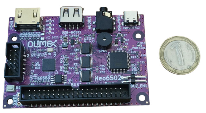
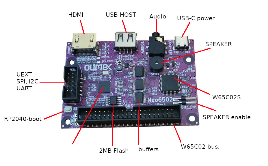
The board size is only 80×55 mm but do not be fooled this is complete 6502 computer with:
HDMI output
USB host for keyboard
Audio output on 3.5mm jack
Small speaker
UEXT connector with +3.3V, GND, I2C, SPI, UART
6502 BUS 40 pin connector with all 6502 signals on it!
RP2040 with 2MB Flash to handle all software defined peripherals and RAM
here is the 6502 bus layout:
When these will be available for sale now depend on how quick we can develop the firmware for RP2040 and W65C02.
There are already some people who shown interest in the firmware development for both RP2040 and W6502, and actually there is work in progress for Neo6502 basic done at:
AgonLight2-Proto is small board with dimensions 100x80mm. It allows you to fast prototype hardware concepts and ideas for AgonLight2 computer. These are the board features:
IDC connector 34 pin for connection on AgonLight2 GPIO
3mm RED LED for 5V power indication
3mm GREEN LED for 3.3V power indication
Sea-of-Pads
GND and 3.3V bus connecting vertically all pads on the left edge
GND and 5V bus connecting vertically all pads on the right edge
Dimensions 100x80mm
3 hex distance spacers for keeping board horizontally when ICD connector is plug to AgonLight2 GPIO
I will admit, I have a sentiment for retro computers. This is probably because my career in IT started many years ago with the Bulgarian Apple ][ clone called IMKO2, later renamed to Pravetz 82.
This is also one of the reasons Olimex stepped into the AgonLight production.
AgonLight sparked a lot of enthusiasm and activity, not only here at Olimex. Bernardo Kastrup hit the sweet spot of the Retro Computer maniacs by offering them a small, fast, feature-packed real Z80 machine with plenty of memory. The Facebook group already has close to 1000 members!
There are a lot of posts about why not having a 6502-based machine, and Kyle (mos_8502), Rebecca (RenewedRebecca) and Bernardo (TheByteAttic) are already working on a W65C265 version using the same ESP32 FabGL-based video and audio system.
Two weeks ago, I started thinking, as an engineering challenge, is it possible to build a modern peripheral 6502 computer that is with the lowest possible cost.
Then I put the minimal requirements for my 6502 computer:
It must have a real 6502 processor.
It must have a minimum of 64KB of RAM.
This computer must run as fast as possible. People confirm that the W65C02 from WDC can be overclocked up to 16Mhz. On the other hand, a lot of software depends on instruction execution time for loops, so the possibility to run at a lower 1Mhz clock will ensure backward software compatibility. This can be achieved with a variable clock that can be set by 6502 software.
The computer must have a modern video interface like DVI/HDMI so that you can connect it to your home TV or modern monitor.
Support for a modern USB keyboard.
A sound synthesizer like the popular C64 SID.
The power supply should be via a USB-C connector so that you can use any phone charger with a USB-C cable.
A UEXT connector with modern interfaces like UART, I2C, SPI.
Disk storage for code.
The 6502 bus should be available on a slot/connector so that additional hardware can be easily added on.
The final requirement is to design such a system to be at the lowest possible price, making it an easy purchase decision, similar to what the Raspberry Pi did with a price of $25-30.
This is a good hardware engineering challenge!
After some research I have decided to use the Raspberry Pi’s new dual-core Cortex-M0 RP2040 as an emulator for everything except the 6502.
The RP2040 will emulate:
The RAM memory. The RP2040 has 264KB of RAM, which is plenty of RAM to hold the emulator code and at least 64KB for the 6502. As the RP2040 runs at 133 MHz, there will be no issue serving the slow 6502 with memory read/write operations. If there is more RAM left, we can implement some kind of bank switching, such as 56KB of continuous RAM from $2000-FFFF and switchable RAM banks for $0000-1FFFF. Alternatively, we can define a pointer and block size somewhere in the upper memory location, which can overlap different RAM segments at any address at any time. After all, what the RP2040 will serve at a given address depends only on the pointer, which will show where this data needs to be fetched from.
Initially, I thought of using the Si5153 programmable oscillator, which can clock from 250kHz up to 100MHz, but after checking the RP2040 PWM specs, I found that the RP2040 can also generate a programmable clock for the 6502 from 0 up to 100MHz. This saves us one more IC!
There is already a DVI generation project with RP2040 called picoDVI, which supports 640×480 pixel resolution with RGB565 16-bit color depth. This project loads about 60% of one of the cores in RP2040.
RP2040 has USB host capability, so there are no issues whatsoever in connecting a USB keyboard to it.
There are already RP2040 SID player projects that exist and can be reused for sound generation, such as picoSID.
Although the UART, I2C, and SPI are interfaces that the 6502 originally did not have, we can catch memory location read/write exceptions with RP2040 and emulate a classic PIA or ACIA. Alternatively, we can define some API in memory to access I2C and SPI buffers.
As for disk storage, RP2040 will have 2MB of external SPI flash to hold the firmware, but there will be a lot of free space. The Apple ][ 5″ floppy was holding the humble 114KB, so around 10 classic floppy discs could fit in a little more than 1MB.
One week ago, I posted my idea on the Homebrew 6502 Facebook group and received more than 100 replies with valuable comments and suggestions.
To summarize all the feedback and prevent redundant discussions, here are the FAQ:
Q: Why not emulate the 6502 with RP2040 as well? A: Emulating memory or ACIA PIA is simple, but the 6502 is a complex state machine, and an emulator will never be 100% accurate. Even N6502 and W65C02 have differences, and we want to have a REAL processor.
Q: Have you checked the CommanderX16 project? You may get inspiration from it. A: I have seen this project, but it is over-complicated, expensive, lacks modern peripherals, and is slower compared to what I want to achieve. This is going to be a MODERN 6502 computer. The CommanderX16 has no modern interfaces like USB keyboard, HDMI, SID Sound, or SPI/I2C. Additionally, the CommanderX16 costs $500, while we aim to target a $25-30 board.
Q: Why not make it with VGA? I have one in the basement. A: We want Neo6502 to be a MODERN computer, and VGA is 40 years old technology.
Q: Why not use W65C265S or W65C816S, etc.? A: These are not 8-bit and have more address lines to deal with, which will make the design more complex and far from the rock bottom price goal. For those who want a W65C625 computer, Kyle, Becky and Bernardo are already working on Agon X65.
Q: Why not Kickstart it? A: Although Kickstarter is a great advertising platform, it has its cost. Kickstarter/PayPal combination takes 20-30% of the collected funds. We target rock bottom costs for our customers and count every cent, so we will not inflate the prices with 20-30% to use the platform.
Q: Do you have firmware developers for it? A: Not yet, so any help and collaboration are welcome. I have already obtained all the parts together and will have a proof of concept on a breadboard this weekend. Then, we will design PCB and some prototypes in a few weeks. If you want to participate in software/firmware development for both RP2040 and 6502, you are welcome to join us! We will have some free early prototypes to send to developers. Send us email to info at olimex dot com.
We got a few inquiries from customers asking if Olimex is interested in making this project and we hesitated at first due to having the bad experience in the past with Maximite pseudo open source project.
After exchanging a few words with Bernardo via Twitter, we became confident that this is a true open source hardware project.
We checked the schematic and decided to do some small changes.
We decided to re-capture the design in KiCad instead of EasyEDA
The power of the original AgonLight is delivered by a USB-A connector which is quite odd and USB-A to USB-A cables are less popular. We decided to replace it with USB-C connector which is used in all new phones, tablets and devices due to the new EU directive. Usually everyone has such a cable at home to charge and transfer files to their cell phone.
We replaced the Linear voltage regulator with DCDC which delivers up to 2A current.
We added a battery LiPo charger and step-up converter which allows operations even if external power supply is interrupted.
The original design had a PS2 connector for a keyboard and required a USB to PS2 adapter to operate with the more available USB keyboards. We replaced the PS2 connector with a USB-A connector so a normal USB keyboard (which supports PS2) can be directly plugged-in to AgonLight
We routed the AS7C34096A-10TCTR SRAM with 40 ohm impedance lines as per the datasheet
Fixed a wrong signal naming in the ESP32-PICO-D4, which now is updated in the original AgonLight documentation.
Replaced the bare header 32-pin connector with a plastic boxed 34-pin connector following the same layout and adding two additional signals Vbat and Vin which allow AgonLight to be powered by this connector too.
Added a UEXT connector (https://www.olimex.com/Products/Modules/) which allows AgonLight to be connected to: temperature sensors, environmental air quality sensors, pressure, humidity, gyroscope, light, RS485, LCDs, LED matrix, relays, Bluettooth, Zigbee, Lora, GSM, RFID reader, GPS, Pulse, EKG, RTC etc.
We changed most of the components to our component base, which we source and stock in large quantities and allow us to bring the cost down.
The design was completed 1 week ago:
Today the first blank PCBs arrived:
Next week we will assemble 5 pcs to test by ourselves and then send to the original AgonLight developers.
AgonLight will be put on our web and available for pre-order next week with a special Christmas price of EUR 50 for a completely assembled, programmed and tested computer.
If the prottotypes are good mass production will follow and all pre-orders taken to 23.12.2022 will be shipped by the end of January.
We plan to make metal case and other accessories in the near future.
Everyone who has made their first steps with Apple ][, BBC micro, or Commodore 64 remembers the BASIC language, which nowadays is used by almost no one.
A few days ago, I was directed to an interesting project named IchigoJam BASIC. It was made in Japan and it was about creating a small computer with a BASIC interpreter, made on single LPC1114 Cortex-M0 ARM controller from NXP with only 32KB of Flash and 4KB of RAM.
Ichigo means Strawberry, so this keeps the tradition PCs to be named on fruits.
Although it is built on tiny resources, IchigoJam BASIC has quite an impressive list of commands including I2C read and write!
The composite video generation is made via a couple of resistors, and the keyboard is connected with a simple USB-A connector, so with just a few components you have a small personal computer!
And this is not everything, the same hardware has firmware for Javascript called IchigoLatte , for Ruby called IchigoRuby, for IchigoFORTH and here.
On top of this, if you want to try IchigoBASIC you can do it on the web. How cool is that?
Needless to say, I wanted to try this project. I choose our LPC-H1114 board as it has almost everything already pre-soldered.
I had to connect:
for power supply:
LPC-H1114.pin50 – to GND
LPC-H1114.pin49 – PWR to +5V DC
for firmware update:
LPC-H1114.pin46 – to USB-Serial Tx
LPC-H1114.pin47 – to USB-Serial Rx
LPC-H1114.pin4 – to GND
for Videop output
LPC-H1114.pin27 – 470 ohm to video connector
LPC-H1114.pin28 – 100 ohm to video connector
for USB keyboard connector:
LPC-H1114.pin23 – DP
LPC-H1114.pin14 – DM
You can update the firmware using the instructions here.
If you did everything correctly when you apply the power supply you will see on the monitor the text “IchigoJam BASIC 1.4.2 by jig.jp”:
Then you can use the keyboard to write your program!
You can repeat the project with quick dirty wire connections like I did:
What you need is a LPC-H1114, a Video RCA jack, a USB connector for the keyboard, a small monitor, a keyboard, and some jumper wires.
This project would be a very good fit for some next Soldering workshop as it has few components but it completes a fully functional BASIC/Ruby/JavaScript/Forth computer.
With the current state of COVID-19 probably TuxCon would be postponed for the Autumn, so there is plenty of time to make a small PCB for soldering 🙂
IchigoBASIC has a button, an LED, plays music on a buzzer and you have access to 4 Digital Inputs and 6 Digital outputs and I2C interface connector.
Too bad most of the educational stuff is in Japanese and needs translation.
Duinomite-MINI, MEGA, eMEGA boards were made specially to run BASIC on PIC32 processors, but are well packed with features boards, so people were using them not only with BASIC interpreter but also programming them in C.
There were not high runners, so at one point we were selling just few per month and when the blank boards were out of stock we had hesitated if to run them again or not, with the time lot of people signed for notification when back in stock so we decided to run small batch of all these three and re-stock.


Recent Comments